
Full Build Instructions
This lecture is based on our YouTube video here. This text based lecture will add some convenient coloring to the YouTube video. Giving you links for relevant downloads, making notes of any official changes in suggested build steps, and in some places giving further details that isn’t provided in the video.
Let’s begin.
0. Where to get the hardware
Grab a micro pi zero drone kit here.
Helpful tools for this project: Soldering iron and helping hands
1. Flashing the F405-HDTE Matek with ArduCopter firmware
Video instructions: 7:06 to 15:28
Docs on F405-HDTE in ArduPilot
Docs on the physical F405-HDTE board
Firmware download for ArduCopter on this board. (Make sure to get the _bl version of the firmware)
Download for INAV Configurator (go to Assets and download the package for your particular OS)
Drivers for your board: ZADIG and Silabs
MissionPlanner download
2. Flashing the Pi Zero with the OS
Video instructions: 15:38 to 21:20
Download for Raspberry Pi Imager
Example wpa_supplicant.conf file
# Giving configuration update rights to wpa_cli
ctrl_interface=/run/wpa_supplicant
update_config=1

# AP scanning
ap_scan=1

# ISO/IEC alpha2 country code in which the device is operating
country=US

# network section generated by wpa_passphrase
network={
    ssid="MYSSID"
    psk="YOUR_PASSWORD"
}
Download Advanced IP Scanner
Dependency Steps on Raspberry Pi (Important for python control of drone!)
****What To Do If Your Headless Setup Isn’t Working! 18:39 to 19:35
3. Soldering to the Flight Controller
Video instructions: 21:22 to 27:18
Wire diagram:
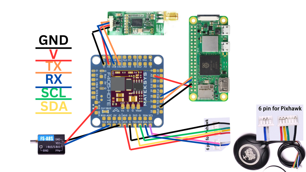
Note! TX on the flight controller goes to RX on the devices (like Pi Zero, GPS and telemetry). Also, RX on the flight controller goes to TX on the devices.
Note Note! The video shows soldering on a BE-880 GPS instead of the ReadyToSky supplied with the kit. This change was made because the ReadyToSky modules get FAR better GPS reception. The same pins/locations are used, just follow the ReadyToSky diagram above to know what needs to be soldered where. You only need to cut the very end off the white connectors. If you cut off too much wire, you won’t have enough slack to get on top of the GPS stand.
4. Soldering and assembling the ESC
Video instructions: 27:18 to 31:21
First, solder the battery connector to the ESC.
Next, Make sure the wiring from the ESC connector to the F405-HDTE is set correctly.
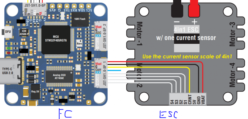
You can use tweezers to lift the slots of the connectors, pull out the wires, and align them so that:
VBAT goes to VBAT. GND goes to GND. Curr goes to CRNT. S1 goes to S1. S2 goes to S2 etc.
Note, the ESC may have a different letter in front of the ESC number (like C1, C2 instead of S1, S2). Just make sure the numbers align.
5. Testing Electronics
RC receiver setup: 31:21 to 32:45
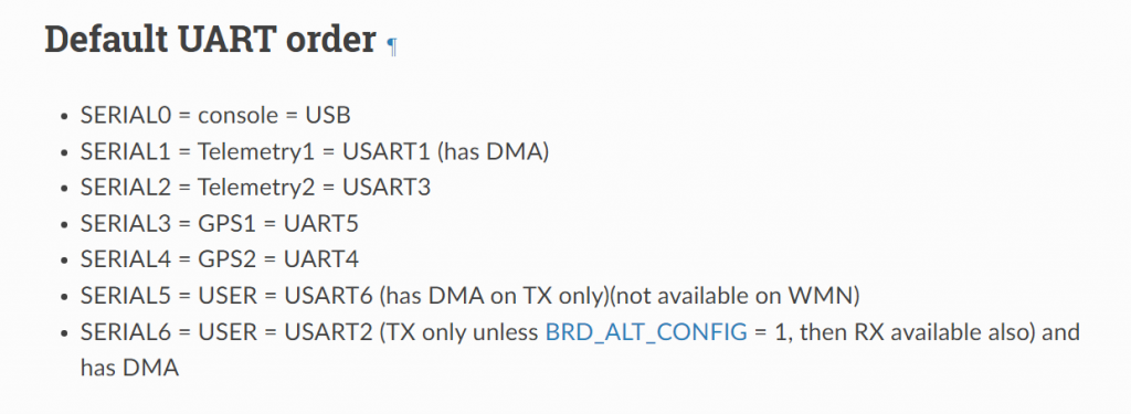
UART (F405-HDTE) to Serial (ArduPilot) Mapping: 32:45 to 32:26
GPS Testing: 36:26 to 37:33
Pi Zero to F405-HDTE Testing: 37:33 to 39:56
Telemetry Testing: 39:56 to 42:19
6. Building The Drone
Video instructions: 42:24 to 54:42
To solder the motors onto the ESC, you will need to extend them by about 1.5 to 2 inches by soldering on more wire. Your pi zero kit has been supplied with these wires in yellow, blue and green colors. Helping hands would be a great aid here. After completed, heat down the heat shrink (also supplied in the kits) over your solder points.
7. Motor Numbering
Video instructions: 54:42 to 1:03:12
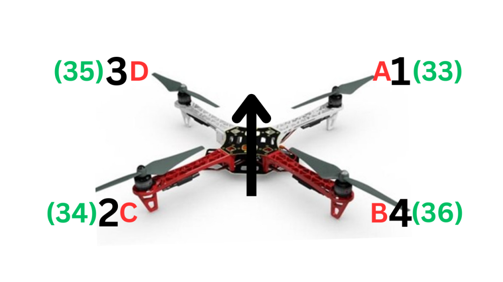
Red is intended motor test motor location
Black is conventional SERVO (motor) numbering into the flight controller
Green is the servo function (33 for top right motor, 34 for bottom right motor, 35 for top left motor, 36 for bottom right motor).
In MissionPlanner motor test, if you hit test motor C, ArduPilot looks for Servo2, reads the Servo2_Function. Lets say when we hit test motor C, that the bottom right motor started moving. We’d just need to change Servo2_Function from the default 34 to 36. So then ArduPilot would know that Servo2 is attached to the bottom right motor.
Perform this for every motor.
8. Drone Build Continued
Video instructions: 1:03:12 to 1:06:44