

Build A DIY Pi Zero Drone
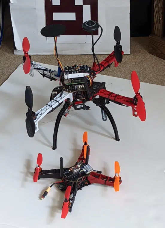
So far in the Dojo, we have shown how to build normal sized drones with the regular sized raspberry pi. In this post, we will show you how to scale down your builds into the micro form factor with a pi zero drone.
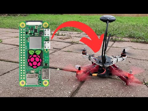
With the former PXFMini Pi Shield solution now discontinued, this guide helps bring Pi Zero drones back to life. If you’d like to build along with this post, check out our Pi Zero Drone Kits, that follows this guide and our pi zero drone video building manual (shown below).
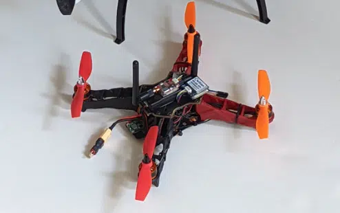
Welcome Spot, a 250mm pi zero micro drone with all the same features as its big brother. It even includes a SBEC voltage regulator and FPV camera system.
The size reduction is primarily due to three things:
1) The frame is 250mm instead of 450mm
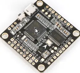
2) The MATEK F405-STD flight controller takes up significantly less volume than the pixhawk
3) The Raspberry Pi Zero W also takes up much less volume than a RPi 4.
If you’re looking for more details on the specific build steps than what are provided in this guide, I recommend checking out our complete guide on how to build your own DIY drone. The steps apply for any drone size.
Features Of The Pi Zero Drone
- Arducopter
- FPV VTx/Camera
- GPS/Compass
- 915MHz radio telemetry
- Raspberry Pi
- SBEC voltage regulator (for camera and RPi)
- 470uF capacitor (to suppress voltage spikes)
One motivation for building this kind of drone is to learn a more refined set of soldering skills since there aren’t any easy pluggable pin connectors. Each connection is made by soldering to 1mm x 1mm solder pads. Additionally, there is a lot of planning and foresight required as the space is very confined.
After building one of these, building larger drones will seem easy.
The F405 flight controller is being discontinued, but there are alternative boards that accommodate the ArduPilot firmware. Note there are a number of RTF FPV drones on the market, but I have not found any that will accommodate a companion computer.
Alternative Boards
| Matek F405-SE 30×30 | 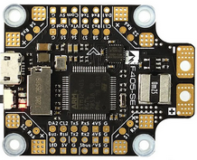 |
| Matek F405-HDTE 30×30 | 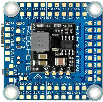 |
| Matek H743-Slim V1.5 30×30 |  |
| Matek H743 Mini V3 20×20 | 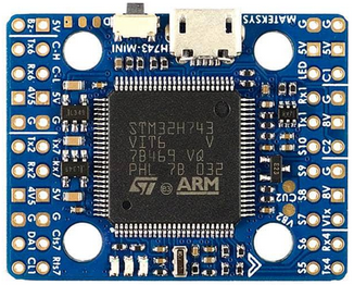 |
| Holybro Kakute H7 with Bluetooth |  |
| Kakute F7 AIO V1.5 | 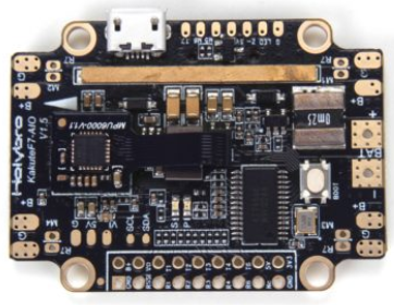 |
Check out our drone flight controller guide for more info on how to select a flight controller.
Parts List For Pi Zero Drone
The present build uses the following materials, but variations on this theme are certainly possible. This list was based on fit, function and affordability.
- Totem Q250 Quadcopter frame ($3.99 at HobbyKing)
- MATEK F405-STD flight controller ($39.90 at Helipal)
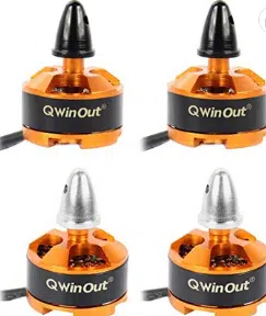
- QWinOut 1806 2400KV CW CCW Brushless Motors ($30.99 at Amazon)
- 5045 CW/CCW 2-blade propellers ($6.99 at Amazon)
- Racestar Rev35A 4-in-1 BLheli_S 3-6S 30×30 ESCs ($43.59 at RDQ)
- FrSky R-XSR 2.4GHz 16CH Micro Receiver w/ S-Bus ($20.99 at getfpv)
- BN-880 GPS Module U8 with Flash HMC5883L Compass ($29.99 at Amazon)
- SiK Telemetry Radio V2 ($59.90 at mRobotics)
- LDARC KINGKONG Wireless AV 5.8G 400MW MINI 40CH VTx ($8.19 at Aliexpress)
- RunCam Nano 4 Mini Cam 800TVL ($19.99 at Amazon)
- Raspberry Pi Zero W ($10.00 at Vilros)
- 22 AWG single-core copper tined wire
- eBoot Mini MP1584EN DC-DC Buck Converter voltage regulator ($10.75 at Amazon)
- 470uF capacitor
- Battery connector / wire
- Vibration pad
- Standoff bolt spacers
- 6” cable ties
- HRB 2600mah 3S 35C LiPo battery ($22.73 at Aliexpress)
- Video monitor ($30-$100 on Banggood)
Total: $340 (without tax and delivery)
If you eliminate the camera system and already have a battery and telemetry radio, you could reduce the total cost to about $197 (July 2022 prices).
Building the Pi Zero Drone
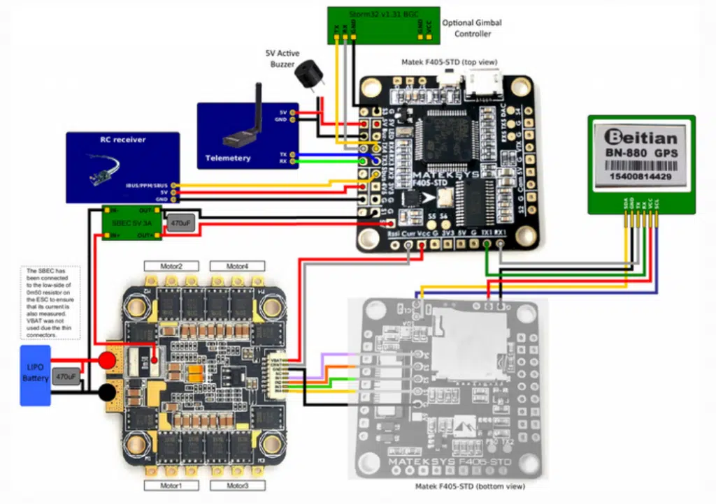
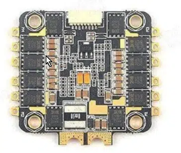
Familiarization with the flight controller is essential before any work is done. By carefully studying the board layout we can identify where the connections will be made and board orientation in the frame.
Figure 4
Prior to any soldering, load up the ardupilot firmware from Mission Planner to confirm the flight controller is not defective. Firmware can be found here. Note this build uses the ‘X’ Frame Type. Also prepare the raspberry pi zero to connect with ssh as per the Dojo instructions. Ensure both steps before moving forward.
Next, build the frame without the top plate and lay out the components prior to soldering anything. In order to access the USB, you will discover that the flight controller orientation might be 90° from the forward direction so the usb port is accessible from the rear (Figure 10). The orientation can be corrected later in Mission Planner.
The esc board will be stacked under the fc using standoffs , but for now leave them separate. Solder connections for each component per the layout above. In this build, single core 22 AWG wire was used to simplify soldering.
Note you can either solder flat or using the through-hole. One trick is to coil a piece of copper wire around the iron to make fine solder joints.
Careful measurements of wire lengths will need to be considered due to the limited space available within the frame.
The following additional tips should help with the process.
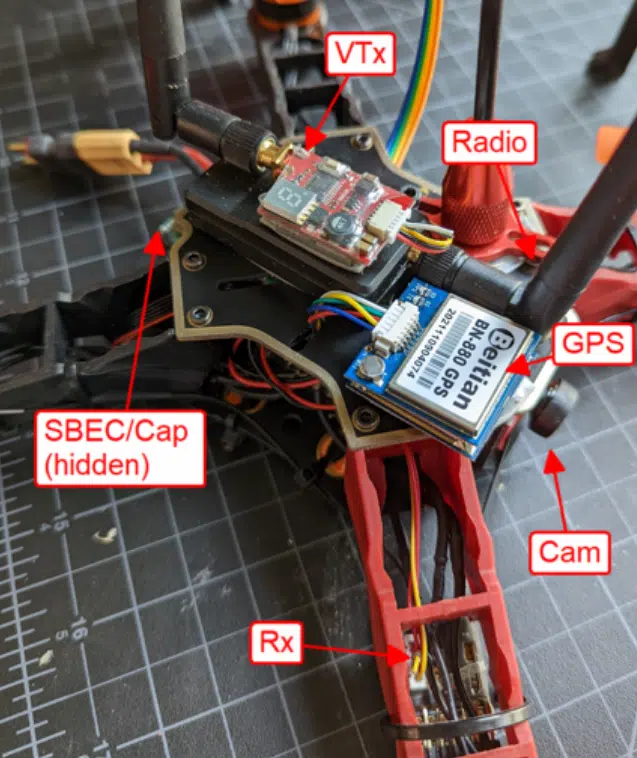
GPS/Compass – Note the Tx1/Rx1 are used here, not for the companion computer as we used in the Dojo course. This GPS comes with an integrated compass and will be placed on the top plate as shown in Figure 2.
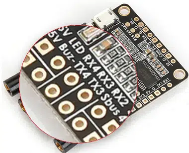
Telemetry radio – Tx3/Rx3 (Figure 5). You will most likely have to cut the radio cable, taking note of the power, ground, and signal wires. The unit will also be placed on the top plate (Fig. 2).
RC Receiver – It is easiest to use a receiver with SBUS which can be soldered to the dedicated pad. This component will be placed underneath a leg (Fig. 2).
Raspberry Pi Zero – Connections are made to Tx4/Rx4 (Figure 5). Normally this is made from the controller to the RPi as Tx>Rx, but I found (perhaps a manufacturing error) it was Tx>Tx and Rx>Rx. The RPi will be attached upside down to the bottom of the frame top plate, so a lot of wire will not be necessary.
Figure 5
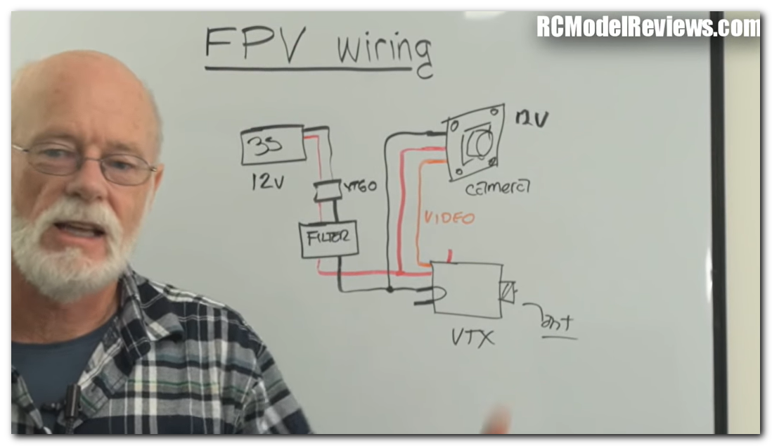
Camera/VTx – The camera, video transmitter, power and ground connections are clearly labeled on the controller. However, if this is your first time connecting a camera, you will need to review the camera and VTx wiring and power specifications. Connections between them might require splicing for shared power or ground. A number of videos explaining this are on the internet and worth taking a look at.
The VTx unit will go on the frame top plate as shown in Figure 2. The camera will be inserted in a special cutout plate in front that comes with the frame.
ESCs and Motors – The motors are directly wired to the esc board which resides underneath the flight controller. Mount the esc board with double-sided tape or vibration pad to the bottom plate.
Figure 7
With the board in the frame, lay out the motors in each correct corner and cut the motor wires appropriate to reach each respective esc. Leave a little extra length to account for possible mistakes. Use 6” cable ties to secure the motors to the frame legs.
Figure 8
From here, solder wires from the respective larger power pads of the 4in1 board to a battery connector towards the rear of the frame (Figure 10).
The battery will go underneath, so the drone literally sits on top of it. Also solder these pads to a voltage regulator and a 470uF capacitor to eliminate power noise. The voltage regulator feeds 5V to the 5V flight controller pad which is used to power the radio and the Pi Zero W board.
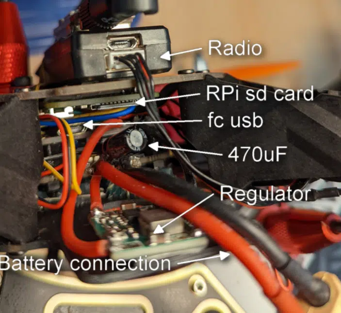
Once the solder connections have been made, carefully assemble the fc over the 4in1 board with standoffs. Affix the Pi Zero to the underside of the top plate with double-sided tape so the sd card is accessible to the rear and usb to one side (Figures 9 and 10).
Figure 9
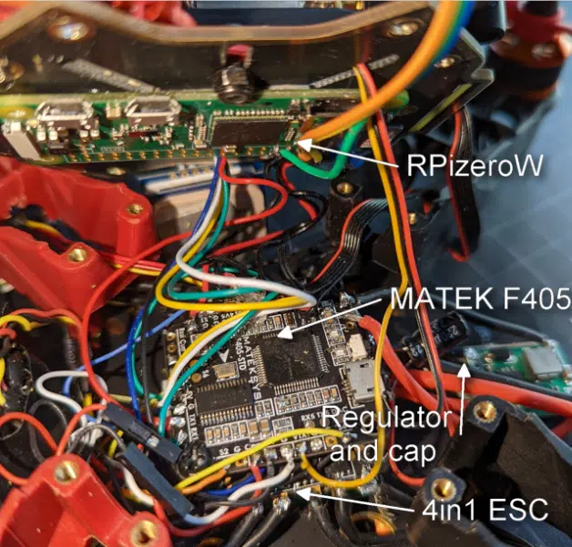
Figure 10
At this point, don’t secure any of the components to the top plate or secure the top plate to the frame. You will want to first power up the system to ensure everything is working. Verify functionality of the FC, GPS, RPi and FPV video output.
Once this is done you can secure the top plate for the first (and hopefully last!) time. Then secure the components to the top plate as shown in Figure 2.
Configuring and Initial Bench Test
Proceed with the calibration process in Mission Planner for Mandatory Hardware. Search in CONFIG for AHRS_ORIENTATION and adjust for any fc offset as mentioned previously.
After this, look under SETUP>Optional Hardware in Mission Planner and use the Motor Test. Observe the spin directions of the motors.
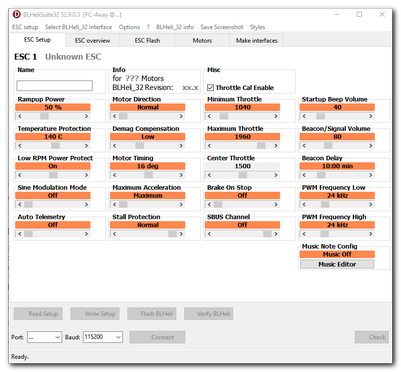
More than likely there will be one or more motors spinning in the wrong direction. To correct this, you will need to use the BLHeli Suite and Configurator. Directions for installing and using this application can be found at Multirotor Guide. You will need a bit of patience and note-taking to get the spins adjusted correctly.
Remember to configure your radio transmitter switches so you can change flight modes and use the Autotune for initial tuning. Test the spin-up of the motors with the transmitter, preferably without props.
First Flight and Tuning
At this point if all components are functional and your drone is calibrated, you are ready to perform a first flight and tune. My suggestion is to start with low altitude flights in Stabilize or Alt-Hold mode. Follow the tuning procedure as described at Ardupilot.org
Once you have a tuned drone, you can upload and experiment with short missions. Keep in mind Spot will not have a long flight time, so keeping track of battery power is advised. You should also ensure to employ safety precautions such as radio Failsafe, and consider a leash for initial missions.
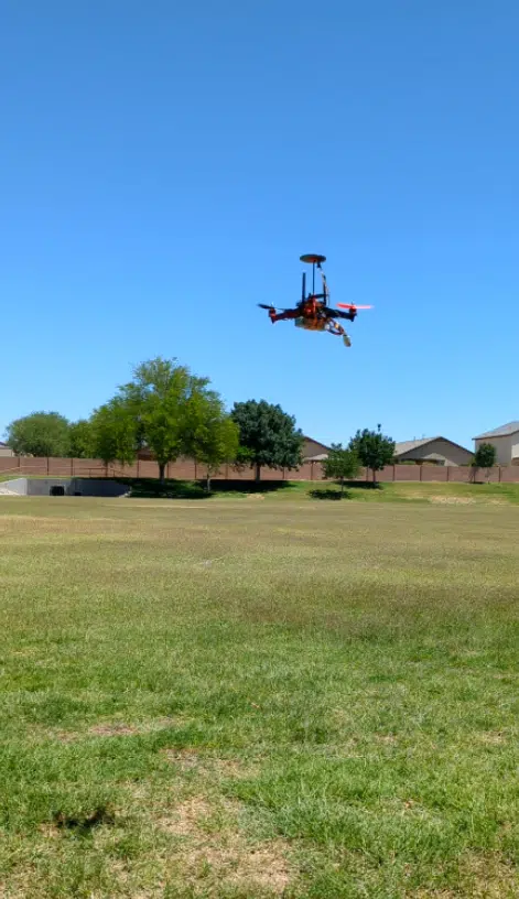
Figure 12
Final Thoughts
It will be interesting to see if further size reduction is possible and accessible to hobbyists. Very small drones have been designed and flown experimentally, so perhaps one day some of this technology will be possible to use. For example, will it be possible to build very small, programmable indoor drones with IR obstacle detection?
Please leave comments as we would like to see your thoughts on building small drones and other configurations you might have used.
References
1 https://ardupilot.org/plane/docs/common-matekf405.html
2 https://ardupilot.org/copter/docs/tuning-process-instructions.html