
DIY Indoor Optical Flow Drone | A Comprehensive Guide
Building a DIY indoor optical flow drone can be difficult if you don’t know where to start, but there’s good news! In this post, I will break down every single step required to build your own optical flow drone.
This is what you will need to follow along with this build:
- An ArduPilot or PX4 drone
- Optical Flow Module
- Rangefinder
- Compass
- 26 or 28 gauge wire
- Soldering Iron
And that’s it!
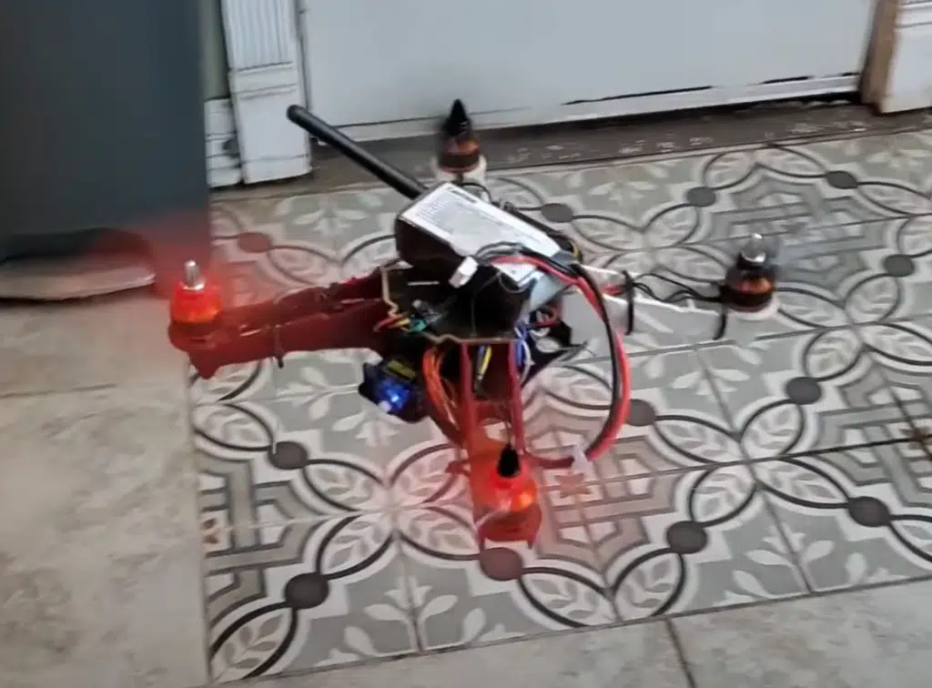
Since we are flying indoors, I preferred to use a smaller ArduPilot drone, so I used our Drone Dojo Micro PiHawk Drone Kit, equipped with the Pi Zero, for this project. If you need an ArduPilot drone to follow along with this guide, the kit even comes with a course that shows you step by step how to put the drone together.
Our larger PiHawk Drone Kit will work as well. If you just want a refresher on how you can build your own drone, check out our guide here on how to build a drone.
Here Is The Goal Of the Optical Flow Drone Project
By the end of the project, you will be able to fly your drone indoors, and have it lock onto a position without GPS. Just take your hands off the sticks and watch the drone loiter in place like magic!
We are using the Matek F405 HDTE flight controller (comes with Micro PiHawk Kit), and the Matek 3901-L0X optical flow module.
If you prefer video, below is what the project that this post is based on.
But before we dig into to build, let’s understand what we are building
What Is Optical Flow?
To summarize, it is a locationing sensor, similar to a GPS. But instead of receiving error corrections from a satellite, a different approach is used.
Why not just use a GPS you may ask? Well, if you plan on flying indoors, your GPS isn’t going to work. GPS modules need a direct line of site to the sky, so satellites can beam down their error corrections to your drone.
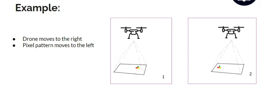
An optical flow module is equipped with a downward facing camera. When paired with a precise rangefinder that tells the drone exactly how far above the ground the it is, it can determine its relative position by measuring how fast pixels move frame over frame.

If the drone knows how far above the ground it is, and how fast the pixels on the optical flow’s camera are moving, it can infer its X and Y velocity.
This means, with a well tuned optical flow module, a drone can loiter in place.. while indoors! You can take your hands off the sticks and the drone will lock in place.
While an optical flow module alone won’t allow you to do advanced indoor autonomous missions, it is the foundation of a stable flying indoor drone. Why is this?
Well put simply, optical flow modules are subject to drift. It never knows exactly where it is at. It only knows where it is relative to its starting point. This means, small errors over time stack up to large overall errors.
To have a fully autonomous indoor drone, you’ll need to pair your optical flow module with a positioning system to supplant what is available to us outside, GPS.
There are many approaches to this, beyond the scope of this post. But to here is a taste of what a complete indoor positioning system could entail:
- Aruco markers placed on the ground that mark known positions in the house. When the drone’s equipped with a camera and computer vision, it could detect arucos and infer it’s absolute position in the house. Or..
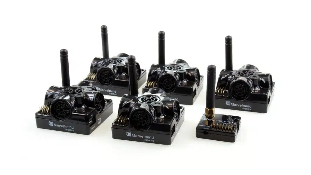
- Marvelmind sonic sensors. These sensors send out pulses to the drone. Depending on how long it takes the sonic wave to hit the drone, the drone can infer how far away from the sensor it is. When multiple sonic beacons are outputting their location, the drone can triangulate where it is at in the house.
These are just a few methods. Regardless of what method you use, the indoor drone will be much, much more stable if it is paired with an optical flow module.
So let’s get into the optical flow drone build.
Optical Flow Modules
Back in the day, there was really only one optical flow sensor on the market for DIYers. That was called the PX4FLOW.
They are still popular, widely used and well supported. As stated before, optical flow requires additional hardware, a rangefinder, to actually work. The PX4FLOW typically comes equipped with a sonic pulse based rangefinder.
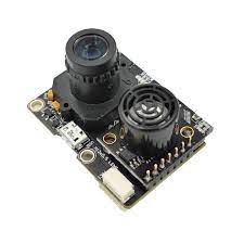
While it sounds good in theory, the rangefinder is wildly inaccurate. So much so, that the ArduPilot firmware actively ignores the readings coming from the onboard rangefinder.
Nevertheless, it’s still a great sensor, and only weighs 17 grams- so it’s still perfect for smaller drones. It uses the I2C protocol to communicate with the flight controller. Back in the day (2015), the module cost around $70, but these days, it costs around $120.
Lately, new manufacturers have been spinning out new optical flow boards.
The HereFlow from IR-Lock is one example. It communicates over the CAN protocol, is more lightweight and smaller in profile, but is a bit an the expensive side at $125.
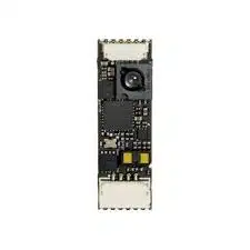
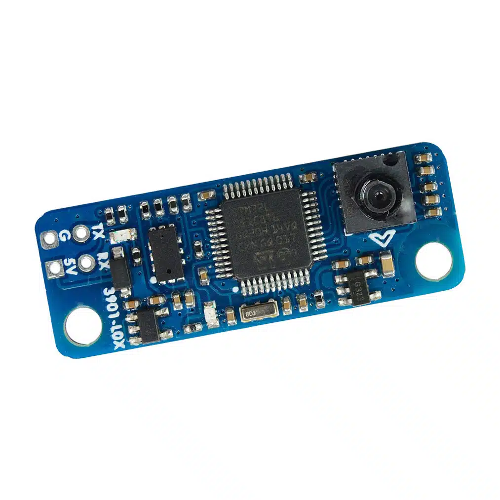
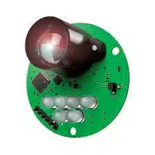
The module I ended up going with for this project is the Matek 3901-L0X. I chose it because it is also lightweight, comes with an onboard rangefinder (more on that in a bit), and only cost $30!
The Matek 3901-L0X communicates over the MSP Multiwii protocol.
One thing to watch for on the 3901-L0X. The stock firmware available from ArduPilot may not come with MSP activated. That means you can’t just flash your board from MissionPlanner, you’ll have to build your own firmware.
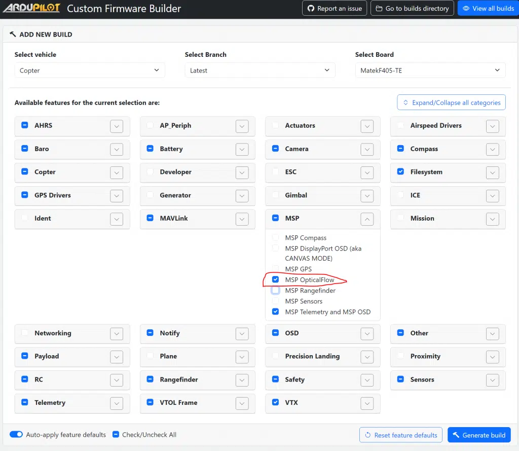
Not to worry! This is very simple. ArduPilot even made a site you can easily do this on. Here’s how I did this for a Matek F405 HDTE board.
- Head on over to custom.ardupilot.org
- Click the “Add a build” button
- Select your flight controller (for the Matek F405 HDTE, select MatekF405-TE)
- Click on the MSP dropdown, and make sure the “MSP OpticalFlow” box is checked
- Hit “Generate Build”
- Wait about 5 minutes for the build to finish
- Download the build
- Flash your flight controller with your build in MissionPlanner or INAV Configurator
Of note, the other optical flow boards shouldn’t require any special firmware builds, as they communicate over buses that are already active by default.
Here’s a list of optical flow boards that will work in this project
- PX4FLOW (I2C protocol, $120)
- HereFlow (CAN protocol, $125)
- Matek 3901-L0X (MSP protocol, $30)
Installing the Optical Flow Board to the Flight Controller
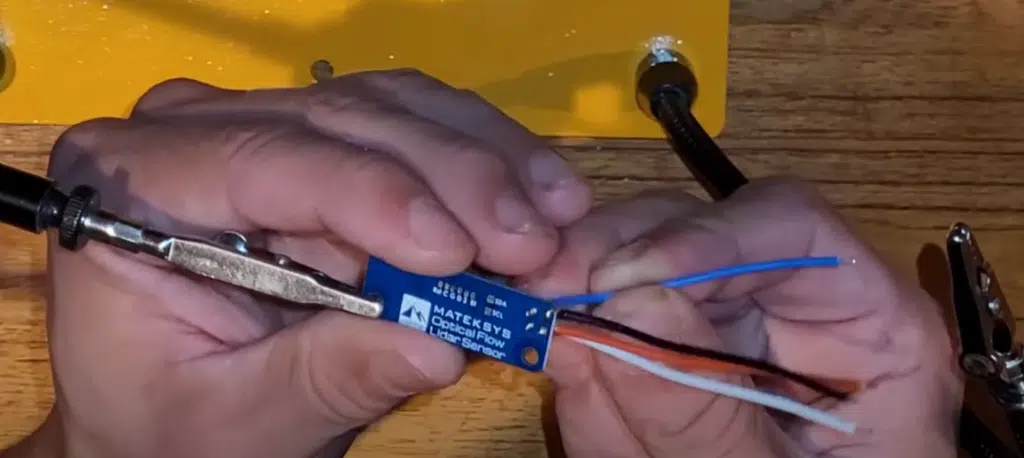
This step will be different depending on what flight controller, and what optical flow module you use. There are too many combinations to go over them all, so I will walk you through how to set up the Matek 3901-L0X optical flow board with the Matek F405 HDTE (flight controller that comes with our Micro PiHawk kits).
You’ll want to get a soldering iron, and some thin gauged wires. We’re going to be soldering directly to the board.
Map out where you’d like to place the optical flow board on your drone. Remember, the module must be facing the ground and ideally towards the center of the drone. Once you know where it will mount, you’ll know how much wire you need to cut.
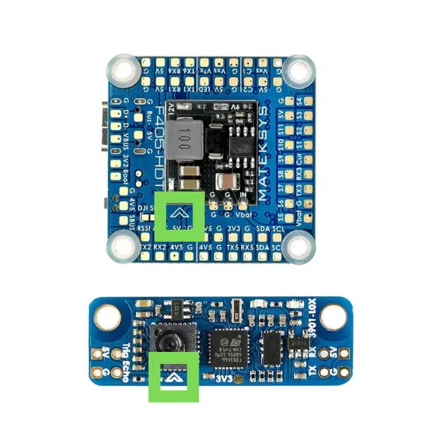
Here is the wiring diagram for connection the optical flow module to the flight controller.
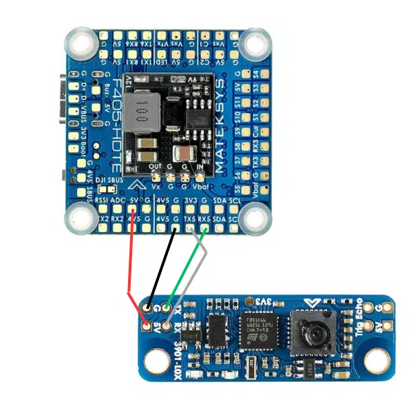
Remember, TX goes to RX, and RX goes to TX for UART communication. Look for the TX5 and RX5 on the F405 matek HDTE, this is the UART buss we will be using for optical flow. This is important to remember for later, when we set up the parameters in ArduPilot to look at this bus for Optical Flow.
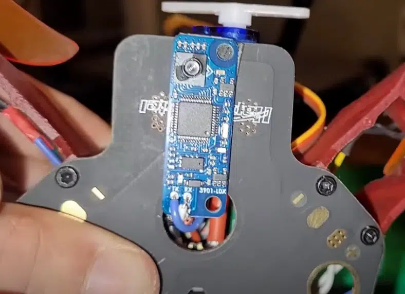
Once the solder connections are made, I simply used some mounting tape to fix the optical flow module to the bottom of the drone.
Setting Up Optical Flow Parameters In ArduPilot
The parameters will be different depending on what optical flow module you used. Here is the in depth docs for the 3901-L0X.
FLOW_TYPE = 7
FLOW_FXSCALER = -800
FLOW_FYSCALER = -800
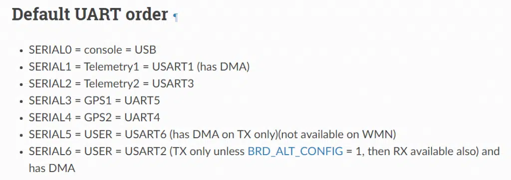
SERIAL6_PROTOCOL = 32
SERIAL6_BAUD = 115
Of note, the TX5 and RX5 indicates that this is the UART channel 5 on the board. BUT, this does not translate to SERIAL5 in ArduPilot, it actually translates to SERIAL6, as their docs show.
Matching The Heading of the Optical Flow Module To The Flight Controller
The next crucial step is making sure the flight controller knows which way the optical flow module is pointing.
You’ll notice on the Matek F405 HDTE, there is an arrow pointing towards the front of the drone. There is also a module pointing towards the front of the optical flow module.
Ideally, these two arrows are pointing in the same direction. If they are not, no worries! We can tell ardupilot their offsets via parameters.
We will do this with the FLOW_ORIENT_YAW parameter.
Basically, if the two arrows are pointing in the same direction, there is a 0 degrees offset so no work is needed.
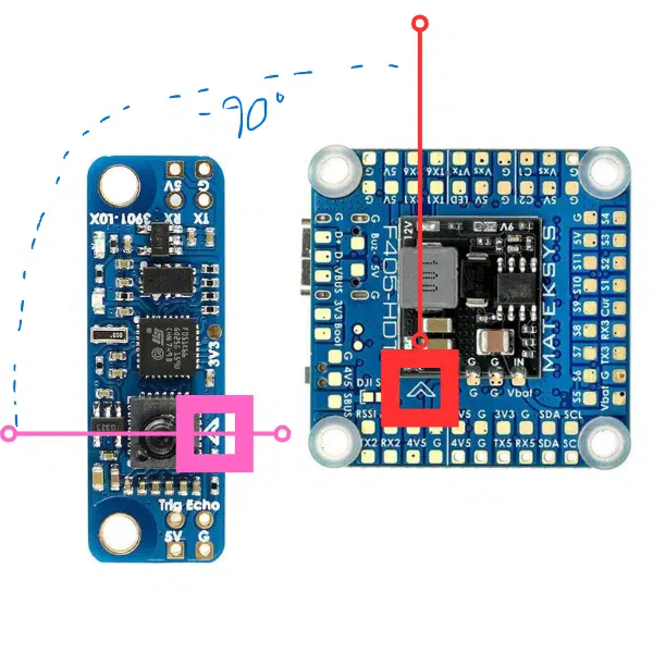
If the module is rotated clockwise from the arrow of the flight controller, those will be positive centi-degree offsets. If the module is instead rotated counter-clockwise, those will be negative centi-degree offsets.
Here’s an example. In the picture below, the optical flow module is rotated 90 degrees counterclockwise from the flightcontroller. So we’d input a -9000 for FLOW_ORIENT_YAW
Additional Parameters For Indoor ArduPilot Flight
Since we’re flying indoors, we need to deactivate all parameters that depend on GPS, and deactivate all return-to-launch failsafes.
Set the following parameters to these values:
- AHRS_GPS_USE = 0
- BATT_FS_LOW_ACT = LAND
- FS_THR_ENABLE = 0
- FENCE_ENABLE = 0
This will ensure safe(r) indoor flight.
RangeFinder
I mentioned earlier that the Matek 3901-L0X has an onboard rangefinder. However, I had terrible results using this. And the rangefinder would work indoors for anything above 1 meter.
For this reason, I highly suggest installing a more powerful rangefinder, because if the rangefinder data breaks while you’re in an indoor loiter, the drone will likely aggressively crash.
There is a plethora of rangefinders available and work with ArduPilot. The more range a rangefinder has, the more expensive it will be.
If you need to fly high, then I recommend the LEDDARONE Rangefinder, which supports up to 40 meters. It costs about $135 and communicates over the UART
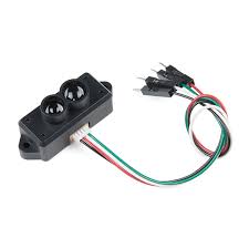
For me, I’ll be flying my indoor optical flow drone at low altitudes, so the TF-Mini Plus is a perfect rangefinder candidate. It has a range of up to 10m.
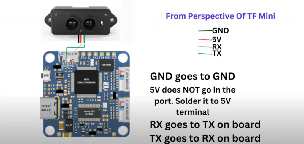
To work the TF Mini rangefinder with the Matek F405 HDTE, it needs a UART connection and 5V. Since all other solderable UART ports are used up on my build, I opted to use UART4 on the Matek F405 HDTE.
This actually is only accessible via a connector that comes with the F405 board. You’ll wire in only TX and RX to the connector. We can’t use power and ground of the connector, because it actually supplies 12 volts.
This is enough to fry the rangefinder (speaking from experience here). So we’ll need to make a Frankenstein cable that solders 5V and GND to the breakout board of the F405 Matek HDTE, and then has TX and RX in the white 7 pin connector to reach UART 4 of the flight controller board.
Don’t worry, I break this all down in this video at 18:50. Here is the wiring diagram as well. It’s not as bad as it sounds.
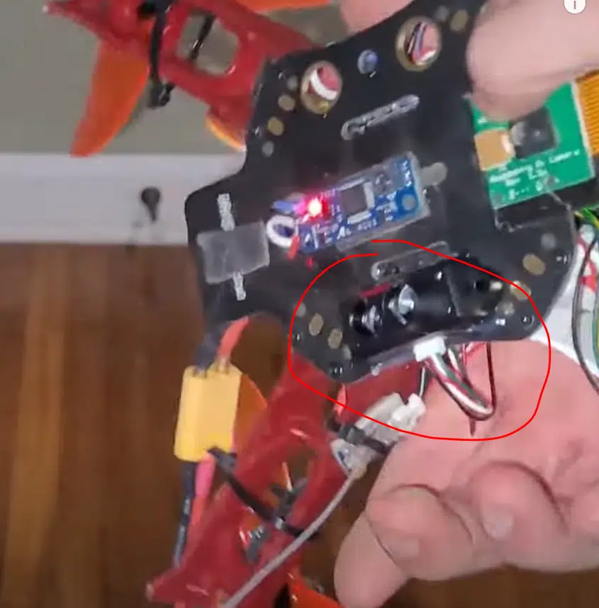
After the connections are made, I once again used some mounting tape to fix the rangefinder module to the bottom of the drone.
Rangefinder Parameters
Once the rangefinder has been installed, we need to tell ArduPilot to use it. This is once again done with parameters.
In this case, UART4 equals SERIAL4 in ArduPilot. So we’ll modify the SERIAL4 parameters.
SERIAL4_PROTOCOL = 9
SERIAL4_BAUD = 115
RNGFND1_TYPE = 20
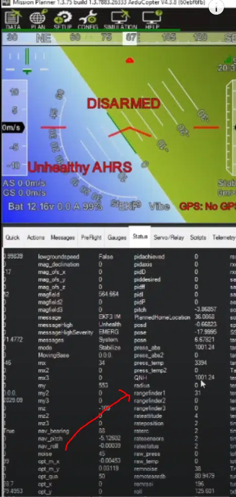
To verify that ArduPilot is using the rangefinder, go to the status tab in MissionPlanner, and look for the RNGFND1 reading. It should be reporting the distance from the rangefinder to the closest object in centimeters. If you’re seeing a non-zero value, congrats!
There’s just one more piece of hardware we need to install
Compass
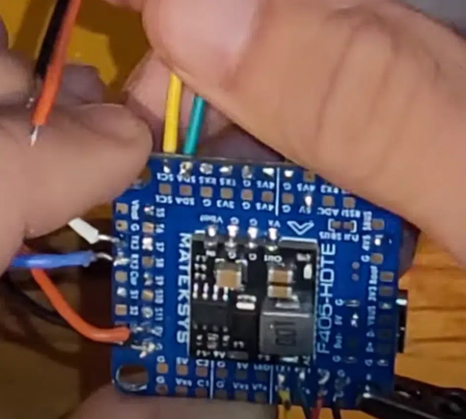
Most flight controllers come with an onboard compass. However if you’re using the Matek F405 HDTE, there is no internal compass. So you’ll need to install your own.
You may be thinking since you’re flying indoors, you don’t need a compass. Or perhaps that it wouldn’t work. This is not correct. You’ll need a compass even if you are flying indoors.
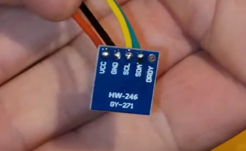
I’m using the QMC5883L compass, readily available on amazon and supported by ArduPilot.
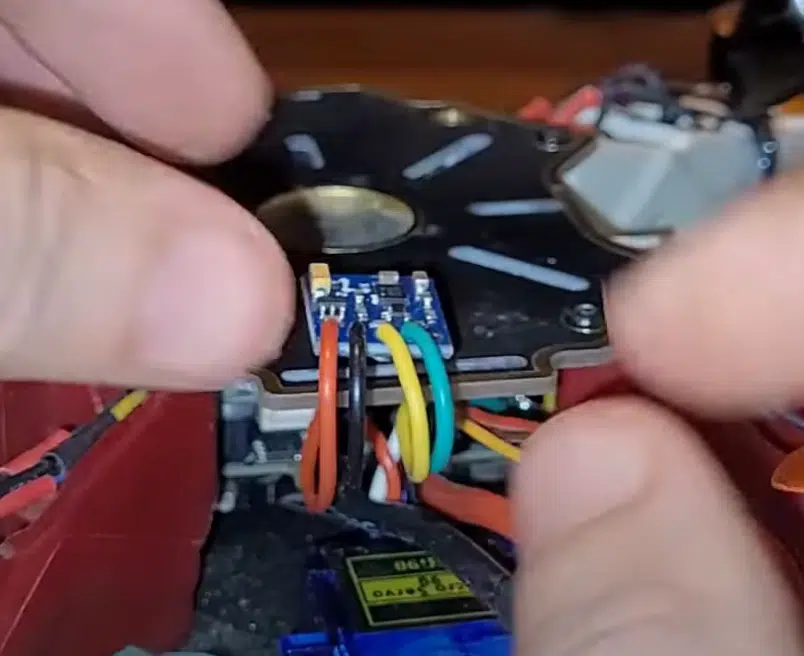
Thankfully, installing a compass is easy. Just solder wires from SCL, SDA, 5V, GND from the flight controller to the compass, and mount it with mounting tape.
With a compass, it will automatically be detected by ArduPilot if it is present- so no parameters will need to be adjusted in this case.
Once installed, go over to Mission Planner, SETUP, Compass, and ensure a compass is present in the list.
Calibrating The Optical Flow Module
Now that you have all the hardware set up and in place, we can begin advancing in the build.
We’ll need to ensure that the reported speeds (in m/s or rad/s) of the IMUs match the data coming off the OpticalFlow module.
Here is the calibration guide from ArduPilot.
But it is a straightforward process. Make sure LOG_DISARMED is set to 1, and power up the drone.
Then just hold the drone about chest high, and tilt the drone back and forth about 10 times about the pitch axis, and then the roll axis.
Then, download the logs and pull them up in MissionPlanner by going to DataFlash Logs > Review A Log and select your log.
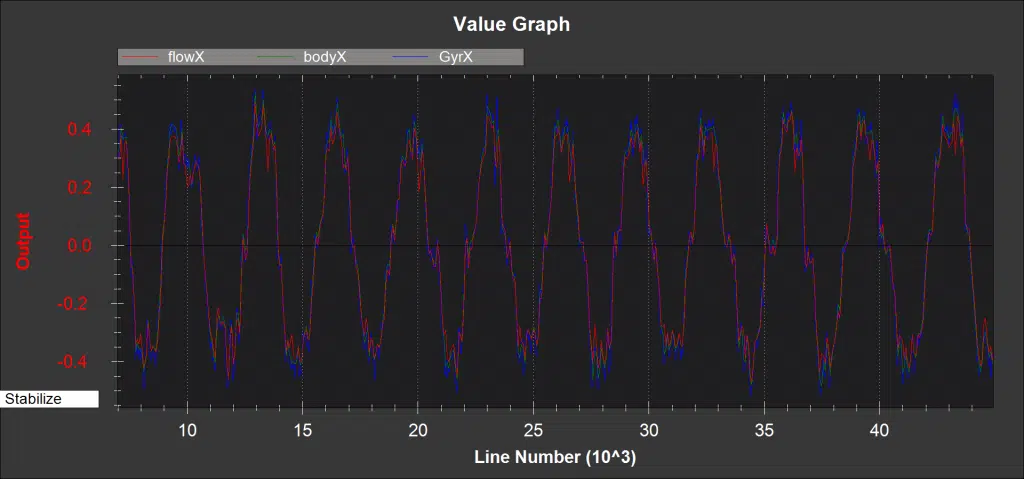
After that, plot the following together:
- OF > flowX, bodyX, IMU > GyrX
- OF > flowY, bodyY, IMD > GyrY
What you want to see is all of the X and Y axis data flowing together during your tilts. Don’t worry about the noisy data when you weren’t tilting about that axis. Here’s an example of a good readout.
Common issues here that are found is the flow data being out of phase with the IMU data. Remember the arrows I mentioned earlier pointing towards the front on the flight controller and optical flow board?
If your data is out of phase, this commonly points towards an incorrect FLOW_ORIENT_YAW entry. Measure again and make sure that parameter is set up correctly.
Loitering Indoor With Optical Flow
Now, we are ready to fly indoors. Set up your flight modes to the following in MissionPlanner:
- Stabilize
- PosHold
- PosHold
- PosHold
- PosHold
- Land
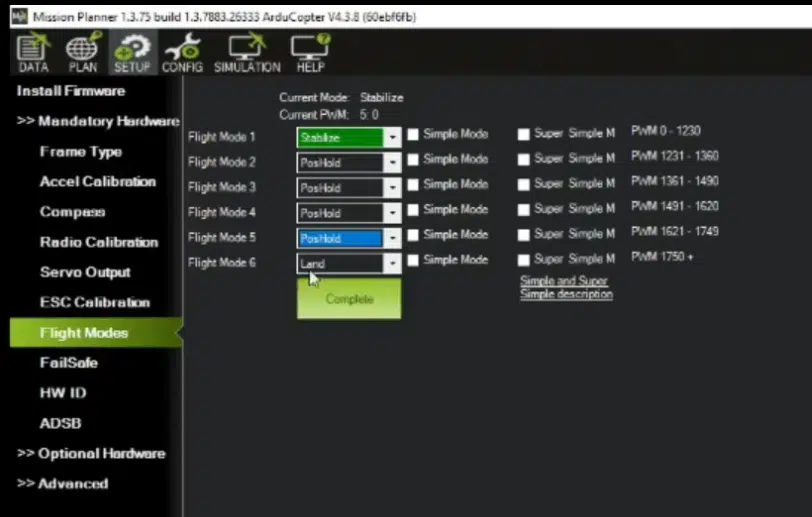
This way, you can takeoff in stabilize mode. At this point, the drone is only responding to your RC sticks, and is not using the optical flow data.
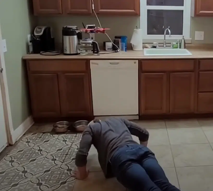
Once you turn your flight control knob to the middle, you’ll be in PosHold mode. Once converted, you should begin to see your drone hover in place without even moving your sticks!
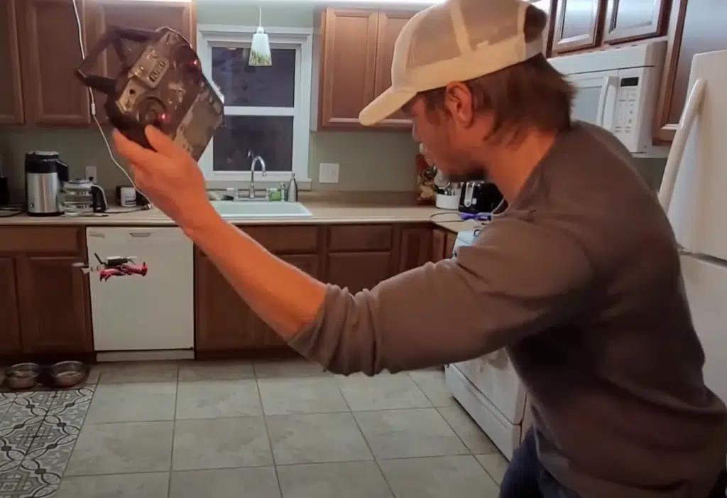
This is the magic of optical flow unleashed. I even got a bit cocky and hit some pushups under the drone without the RC controller while it was hovering in place.
If you got to this point, congratulations on your successful project! This is the first step in unlocking indoor autonomous flight- bravo!
Next Steps
Now that you’ve gotten to this point, I’m sure you’re wondering what’s next.
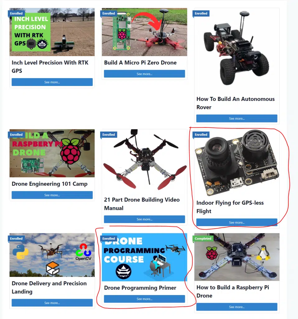
Well we have more tutorials that I think you’d love. If you become a blue belt member, you get access to all of our courses and projects. You could hit up our drone programming primer, that teaches you how to control your drone with Python, or even take our Indoor Drone Flight course to get a better grasp of Optical Flow.
Our goal is to empower you to build crazy things. Build the next tech startup, or dive into some crazy scholastic research. What will you build?